Heat Exchange and Electricity Laboratory
Main Equipment
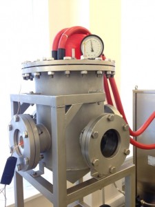
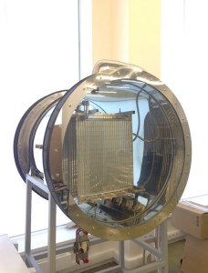
Research installation of boiling processes on different surfaces
Purpose: an experimental and theoretical study of heat transfer on a microstructured surface for the intensification of the boiling process. The working mediums are different refrigerants.
- Boiling in a large volume at a pressure of up to 10 bar
- Easiness of data registration
- Getting experimental data on temperature flows on various microstructured surfaces during the boiling of freons at different pressures.
- Study of the microstructured surface influence on the initial nucleation in a liquid and the possibility of reducing overheating.
Condensation installation
The tasks which are realized in a condensation installation include the study of single-phase convection, the effect of different surfaces and the design of a heat exchanger on condensation. It is also possible to investigate the superhydrophobic coatings using this equipment.
The installation includes: evaporator; chamber with condenser; additional condenser; cooling thermostat, vacuum pump.
Testing facility for heat exchangers Water-Air
The unit is designed for testing and controlling the characteristics of heat exchangers with gas-liquid processing medium.
Installation setup includes:
- Air blower FPZ providing air flow from 2 to 200 kg / h at a pressure of 0.5 bar;
- Two Leister LHS heaters that heat the air flow to the heat exchanger up to 450 ° C;
- Cooling heat exchanger Spin-Cell;
- Measuring equipment.
Heat pump installations with refrigerant and carbon dioxide
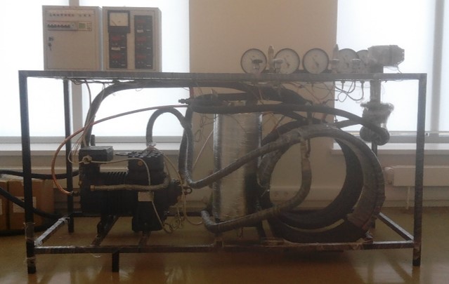
A number of heat engineering tests were conducted at the experimental stands to assess the energy efficiency of Heat Pumps. Purpose: the use of mixed refrigerants and the prototype installation on carbon dioxide for the study of heat and mass transfer in power equipment.
Application of Heat Pumps allows to reduce the coefficient of primary fuel use, to reduce heat losses in heat networks, to create dual-purpose cooling and heat supply systems, in which the exergy efficiency is significantly higher in comparison with single-purpose systems.
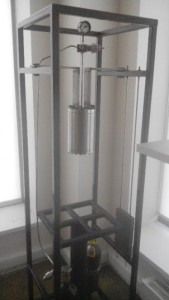
Experimental installation for the study of thermal stabilizers up to 2.5 m in length for power and transport infrastructure facilities.
The installation consists of two parts: a container with model soil and a thermal stabilizer with measuring equipment and a refrigeration unit.
The tank is designed to observe a cylindrical temperature field around the thermal stabilizer. The model soil can be translucent for optical observation of the movement of the freezing boundary.
Models can consist of ground glass particles, micro- and nanoparticles, aluminum oxide, silicon oxide and water.
The thermal stabilizer is collapsible, which allows to explore various working fluids and coatings.
Climatic chamber
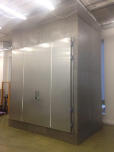 The ability to test large objects
- Camera dimensions: 4,7m height; 3,5m width; 2.3 Depth
- Each equipment which is operating in the Far North requires verification at -40 C
- The camera is designed to create a temperature range from -70 to +150 ° C
Hydrophobic coating installation with use of carbon dioxide and supercritical fluid chamber
Auxiliary equipment
- Air oil compressor P=20 bar
- Air funnel temperature up to 200C
- Thermostatic oven Huber Unistat 530w 24 kW at +250 C; 1 kW at – 50 C
- Air blast with heating component LHS61L
- Electric power supply 0-15V-1A+ 5V/1A
- Electric power supply Keysight N8741A DC Power Supply 300V, 11A, 3300W
- Laboratory three-phase autotransformer 0-450 V
- Laboratory autotransformer TDGC2-3B, 1xANALOG, 0-250V-12A
- Converter OMRON 3G3MX2-A4110-E 15 kW
- Thermostatic oven Huber Unichiller 025w-MPC plus
H2SMART
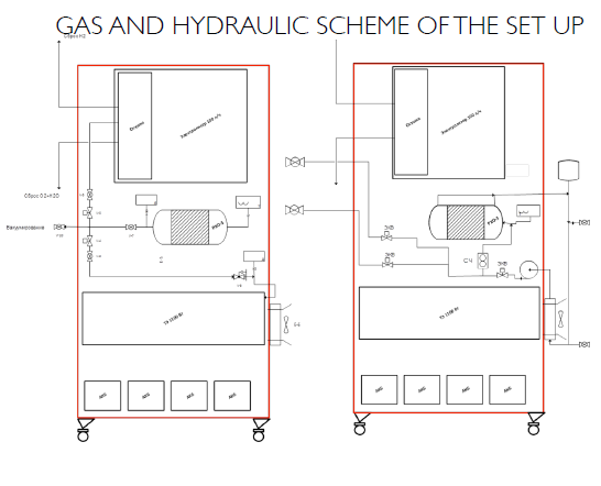
The goal of the research is to create an experimental cogeneration energy system with hydrogen energy storage H2Smart having a power of 1 kW. This system is
designed to be an experimental energy storage system in Smart Grids and to be an essential part of educational process in Energy Systems programs at Skoltech. The
technology ensures quality of electrical energy in micro energy systems that have a load and distributed energy sources through the use of hydrogen energy storage. Hydrogen
is produced by electrolysis utilizing waste energy from the renewable sources. Electricity is generated by PEM fuel cell.
H2SMART IS REQUIRED TO HAVE THE FOLLOWING FUNCTIONS:
Hydrogen generation using renewable sources of energy or the simulation of renewable sources of energy; hydrogen storage in the solid metal hydride form as the
result of a chemical reaction with metallic alloy; utilizing thermal energy of RSE or its simulator; using hydrogen for thermal and electrical energy co-generation;
ensuring the possibility of measurements and control of the main parameters in order to perform experimental investigations
H2SMART CONCEPT AND TECHNICAL CHARACTERISTICS
Maximum working pressure is no more than 1 MPa;
Fuel cell power level 1000W;
Metal hydride reactor metallic alloy – LaNi5;
The amount of hydrogen stored in MH reactor 1000l;
Nominal pressure of MH reactor charging is no more than
0.5 MPa;
Nominal hydrogen consumption rate is no more than 15
norm l/h
Cooling type: water 0…95°С;
PARTS OF THE SYSTEM
ELECTROLYSER H2BOX-100
H2Box-100 produces electrolytic hydrogen that is being used in industrial and research laboratories to supply chromatographs and gas analyzers with plazmoionic detectors and other technological processes that require pure hydrogen. The main component of H2Box-100 is an innovative electrolyzer with solid polymer electrolyte with high proven resource (more than 20000h). Required electrical supply is 200V. H2Box-100 has an electrical control and power conversion efficiency of at least 96,5%.
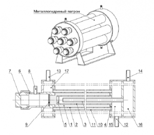
Metallic alloy 1 is placed in an annular cavity, formed by the inner surface of the reaction chamber 2 and the outer surface of the tube 3, which are hermetically sealed with end caps 4 и 5. An absorbing material load is performed through the hole in the nipple 6, that is closed by the lid 7. Hydrogen is sent to the chamber through the nozzle 8. In order to avoid absorbent material particles in the gas piping there is a filter 9 installed in the nozzle 6. Heating and cooling processes of the material are performed by a liquid coolant through the gaps between the camera 1 and the housing 10 (external cooling) and between the tube 3 and fixed inside it tube 11
(internal cooling). The coolant is pumped through the inlet 12, leaves the reactor through outlet pipes 13 and 14 and proceeds sequentially through the manifold 15, tube 3, tube 11, manifold 16 to the conduit 14 and through manifold 15, housing 10 and manifold 17 to the conduit 13. Reactor is filled with intermetallic alloy LaFe0.5Mn0.3Ni4.8.
PEM FUEL CELL E-1100
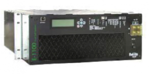 Technical characteristics of PEM FUEL CELL E-1100:
Type: solid polymer electrolyte
Cooling system: air
Nominal power: 1100 W
Nominal voltage: 24/48 V (DC)
Hydrogen consumption: 14 norm l/min; (nominal power 1100 W); The level of hydrogen purity: 99,95%
Multi-machine experimental setup for dynamic stability tests of distributed grids
Goal: The results of the experiments are meant to prove the novel modelling and control methods devoted to extend the stability limits of such systems.
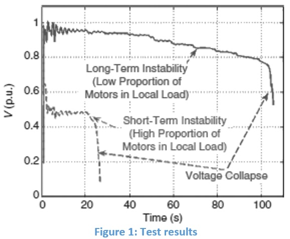
Task: The setup will allow studying the voltage collapse phenomena causing system disruption in power grid with high penetration of induction motor load.
A multi-machine experimental setup is being developed in the framework of the Grant Agreement No.14.615.21.0001 dated 09.09.2014 between the Ministry of Education and Science of the Russian Federation on the topic: “Dynamics stability and control of distribution girds“. The effect of voltage instability and fault-induced delayed voltage recovery resulting in voltage collapse resulting problem in many partial or complete system blackouts is studied.
The setup will represent the distributed network with 3 three-phase induction motors and 3 single-phase induction motors running at constant torque (modelling of compressor application in air conditioning systems). The network is supplied by three-phase AC synchronous generator with variable active and reactive power outcome (output voltage can be maintained 0,5-1,1 pu). The switch models a fault-induced delayed voltage recovery (50-150 ms). The motors’ voltages, currents and speed is observed by means of high-speed data acquisition device (DAQ).
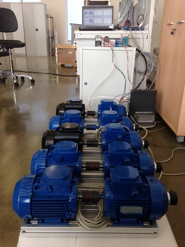
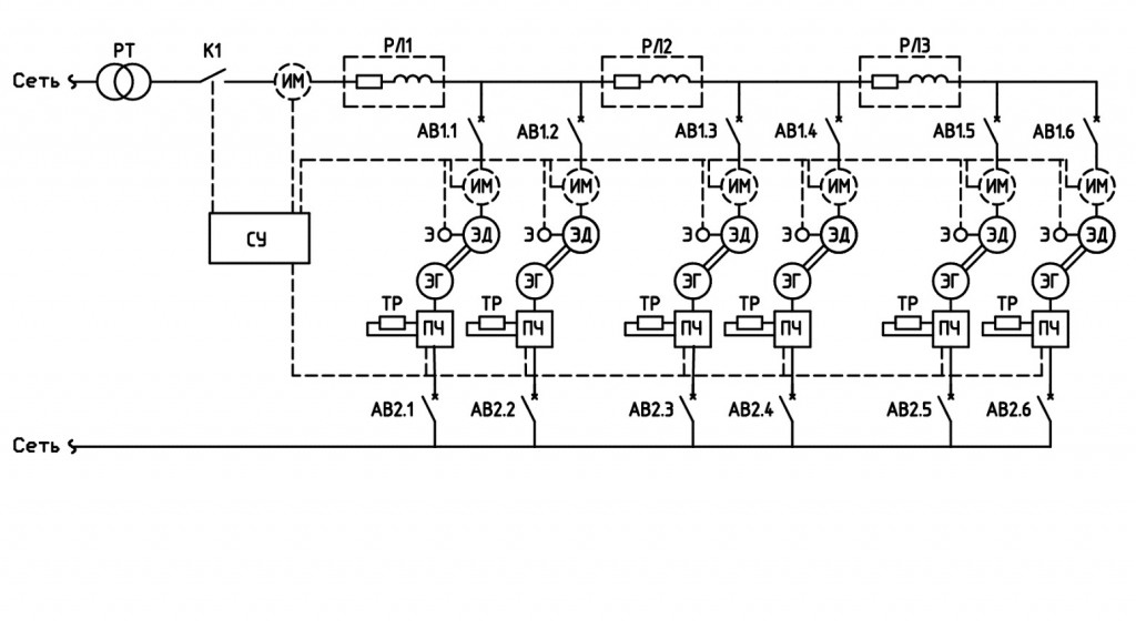 Fig. 1.1 – Functional scheme of the setup
РТ – separating transformer;
К – contactor;
АВ – circuit breacker;
РЛ – distribution line;
ЭД – induction motor;
ЭГ – induction generator (as mechanical load);
ПЧ – frequency converter;
Э – encoder;
СУ – control system.
Real-time Power Quality Analyzer
To use real data for testing future algorithms
